Current Transformer
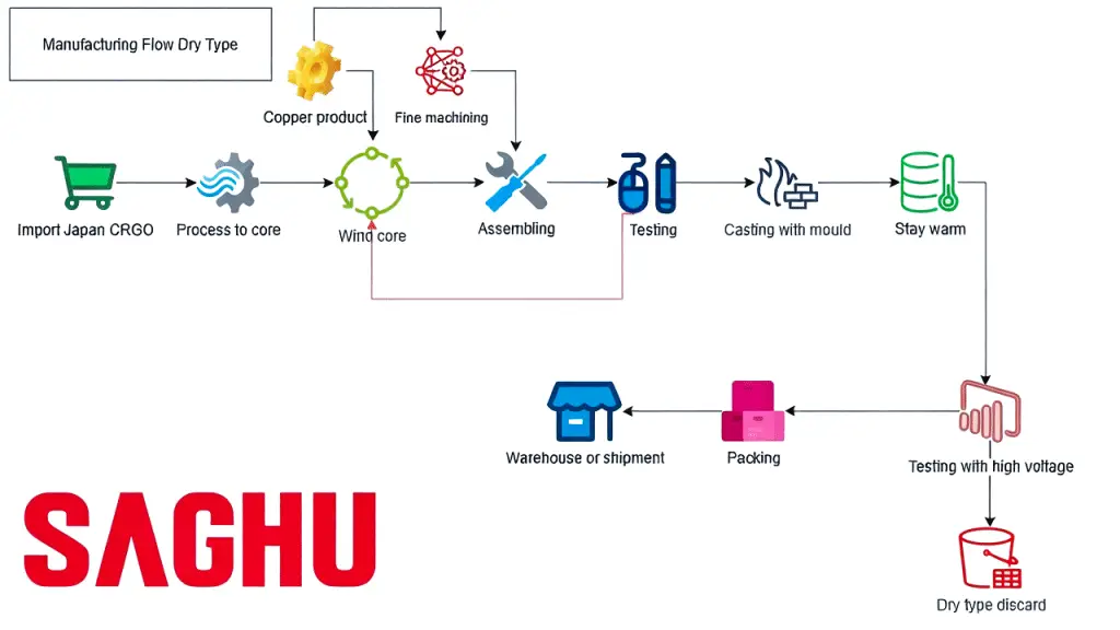
The products are designed in strict accordance with IEC or ANSI standards, and the manufacturing steps meet the technological requirements
Model
Our Products
Precise conversion, secure isolation, ensuring reliable current measurement every time


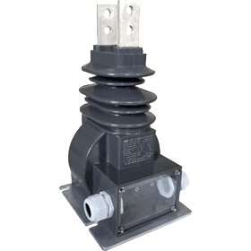
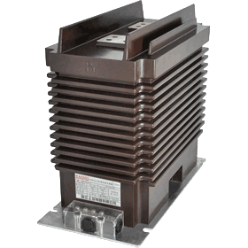
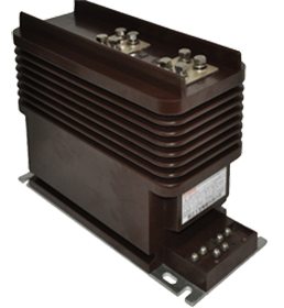
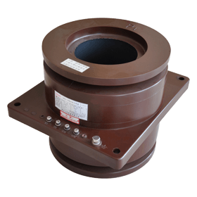
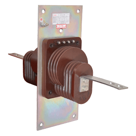
10/11V bushing type Current Transformer
Bushing Type Current Transformer MODEL:3.3-13.8 kV
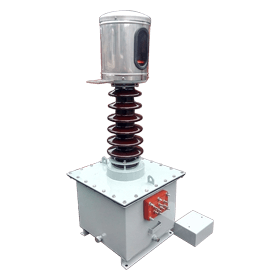
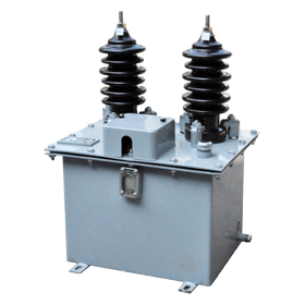
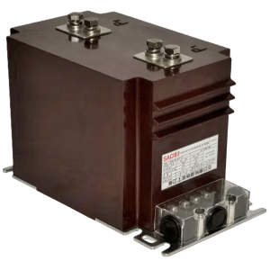
33/36V oil type Current Transformer
Outdoor Oil Type Current Transformer MODEL:33-40.5 kV
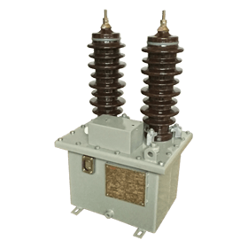

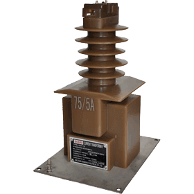
10/11V oil type Current Transformer
Outdoor Oil Type Current Transformer MODEL:3.3-11 kV


Overview
Key Strengths
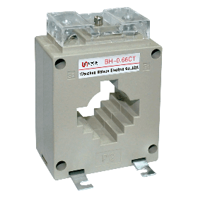
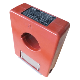
A current transformer (CT) is a measuring transformer designed based on the principle of electromagnetic induction. It is widely used in power systems for energy metering, current measurement, and relay protection.
It converts the high-voltage, high-current on the primary side into a standard 5A or 1A low current at a fixed transformation ratio, while providing electrical isolation between the high- and low-voltage circuits to ensure the safety of secondary equipment and operating personnel.
- High-precision measurement
- Wide-range adaptability
- Stable and reliable
- Multi-layered security
- Flexible installation
Advantages of Choosing Us
Why choose our products?
1
🏅Quality Assurance
Strict quality control, proven over time. Authorized certification, trustworthy.
2
✅Precise measurement
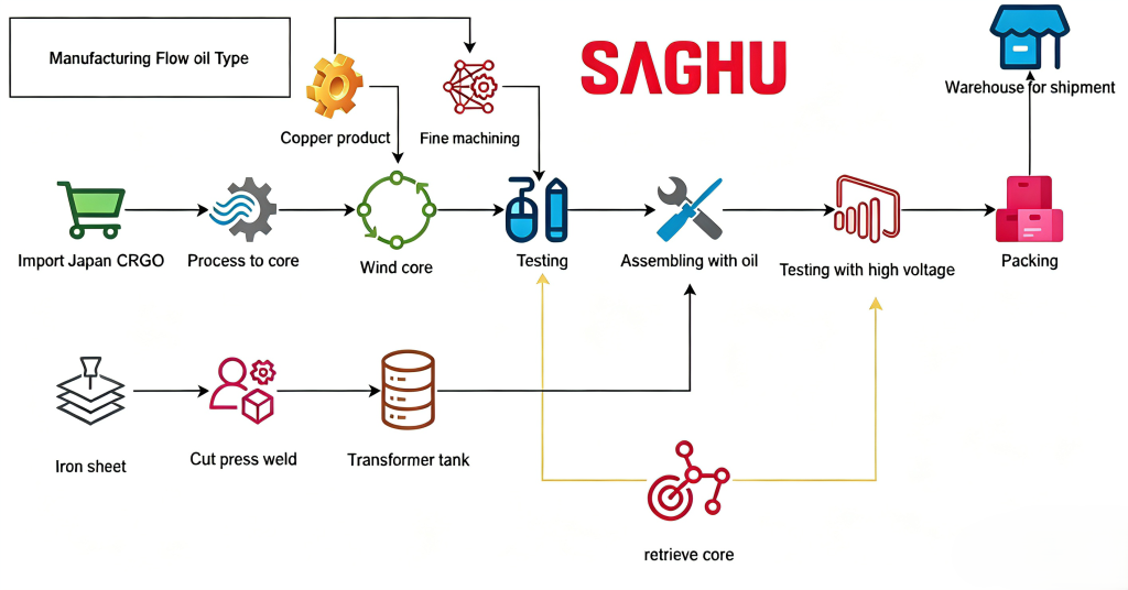
Every product undergoes individual inspection at the comprehensive testing station before leaving the factory to ensure consistent accuracy.
3
🌍Select
Complete range of sizes—everything you need in one place
Main Structure
A current transformer (CT) primarily consists of five major components: the iron core, the primary winding, the secondary winding, the insulation system, the housing, and the terminals. These components work together to achieve current transformation and electrical isolation.
- Iron Core — Magnetic Flux Path
- Primary winding — Series current-carrying
- Secondary Winding — Inductive Output
- Insulation—A Safety Barrier
- Housing & Accessories
Primary winding
High electrolytic copper is used as primary winding, silver base welding material is used at the welding place, and semiconductor shielded paper is wrapped to ensure that the partial discharge tseting data is qualified.
Secondary winding
Large capacity design secondary winding, automatic winding, high insulation and high purity enameled wire, to ensure wide capacity output under standard accuracy.
Quick Q&A
Answers to Some Common Questions About Current Transformers
Q1:Why is it strictly prohibited to open the circuit on the secondary side of a current transformer?
A: During normal CT operation, the secondary side is effectively short-circuited. If the secondary circuit is interrupted (open circuit) during operation, the magnetic flux generated by the primary current cannot be canceled out by the secondary current; the core will become severely saturated and induce
, potentially causing insulation breakdown, equipment damage, or even endangering personal safety. Ensure that the secondary terminals are reliably connected to instruments or short-circuited before performing any operations; disconnecting them while energized is strictly prohibited.
Q2: Does the secondary side of a current transformer need to be grounded?
A: Yes. The secondary side of a current transformer must be grounded at a single point (typically at the terminal box or protection panel). The purpose is to prevent high voltage from the primary side from entering the secondary circuit due to insulation breakdown, thereby ensuring the safety of personnel and secondary equipment
. Note that grounding must be limited to a single point to avoid the formation of ground loops.
Q3: How do I choose the appropriate transformation ratio and accuracy class?
A:
Transformation ratio: The primary rated current is slightly higher than the line’s maximum operating current (typically 1.2 to 1.5 times), with common ratios such as 100A/5A, 200A/5A, and 400A/5A.
Accuracy: For energy metering, Class 0.2S or 0.5S is recommended; for ammeters and monitoring, Class 0.5 or 1; for relay protection, 5P10, 5P20, etc.
Q4: What is the difference between split-core (open-type) CTs and standard through-type CTs?
A: Open-type CTs can be snapped onto existing cables or busbars without the need to shut down power or disconnect wires, making them particularly suitable for power distribution retrofits and the installation of energy consumption monitoring systems; Conventional through-type CTs require cables to be threaded through the core or busbars to be pre-threaded, and are primarily used in new cabinet installations. Both types operate on the same principle, and accuracy depends on the specific model.
Q5: What causes a CT scanner to overheat or emit an unusual odor during operation?
A: Common causes include an open or partially open secondary circuit, secondary load overload, excessive contact resistance (loose terminals), excessive ambient temperature, or insulation degradation. If any abnormalities are detected, immediately shut off the power and inspect the secondary circuit connections and insulation resistance.
⭐We look forward to becoming your trusted electrical partner!